 |
GEER TECHNOLOGIESCAMLESS ENGINE |
 PATENTED |
|
DISK SENSOR + SOFTWARE VS SOFTWARE ALONE INCREASE CAMLESS ENGINE PROCESSING POWER |
- The Disk Sensor is the #1 solution to control electronically timed valves in a camless engine.
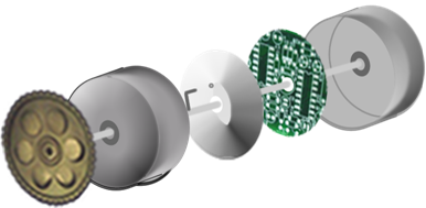
- An electromagnetic actuator found in a camless engine uses 2 signals to control the opening and closing movements of the engine valve. Therefore in a 16 valve engine you can expect to have 32 separately timed signals to operate the valves. The magnetic platter Disk Sensor easily makes available the 32 individual tracks that are needed to supply the signals to the valves. These 32 signals come from 32 concentric circles of which are found on the magnetic platter disk. For each track on the platter you will find a matching magnetic read head. 32 tracks = 32 read heads. The fixed reading heads are mounted over the tracks. As the magnetic platter disk is rotating in sync with the crankshaft, the 32 output signals, in different timing degrees, are sent to the engine computer and then the valve. The magnetic disk platter is timed 2:1 to the crankshaft, just like a camshaft.
- The magnetic disk platters media, or material being read, determines the strength and type of signal. The disk platter can produce analog and digital signals or both at the same time. Hundreds of individual tracks are available for timed information storage on the platter disk, thus allowing for fuel injection and spark ignition timing to be achieved as well. Spark ignition and fuel injection would simply be more dedicated tracks on the disk platter, which leaves a relatively small footprint. If you have a 32 valve engine you may have 64 signals plus 8 fuel injection and 8 spark ignition signals, totaling 80 independent signals. The disk platter easily supports this requirement. * Both intake valves in one cylinder do not have to open at the same time or the same amount when using the Disk Sensor, thus showing great flexibility of the Disk Sensor.
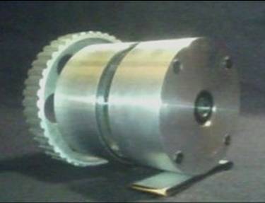
- As the Disk Sensor is driven by the crankshaft via timing belt, the media on the disk is read in real-time by the magnetic heads which are fixed over the tracks. Like a personal computers hard drive where you find mobile read/write heads, there is also a mobile read/write head which is used in the magnetic platter Disk Sensor. This mobile read/write head modifies the track signal strength accounting for wear and other corrections while the engine is running. This allows the fixed read heads to read the modified signals uninterrupted .
- Variable valve lift ~
~Throttle Position Sensor (TPS)
~Referencing the voltage of the TPS signal (0 to 5 volts) for valve lift
- Variable valve duration/timing
~Digital Signal Processor (DSP)
~The DSP delays the valve signal generated by the disk according to the engine rpm effectively opening the valve later, as desired
- Geer Technologies Disk Sensor retains the important 2 to 1 timing ratio that the camshaft utilizes. This ratio is important because of the 4 stroke cycle and the detection and distinction of 720 degrees of rotation from the crankshaft to time the engine valves.
- By timing the Disk Sensors pulley to the crank (2:1); timing issues are eliminated.
- The Disk Sensor supplies the computer with hardware based "cam" signals. The computer then adjusts the signal according to the engine temp, air temp, manifold pressures etc..
- The Disk Sensor offers discrete electronic fuel injection, spark ignition and valve timing signals.