- There are 2 main types of Disk Sensors. 1) The first Disk Sensor uses an electric motor internal the Disk Sensor housing to drive the magnetic platter while the engine is off (This setup is no more complicated than controlling a hard drive electric motor to achieve a particular RPM). This allows a set of isolated valves to be tested while mounted in the cylinder head and while the cylinder head is mounted to the engine block. Explained in more detail below. (This particular sensor is for OEM level rapid testing and high performance tuners). 2) The 2nd Disk Sensor does not have an electric motor internal the Disk Sensor unit to run valves in an engine while the engine is off, but rather this Disk Sensor is driven only by the crankshaft and a timing belt. Both sensors utilize the magnetic platter with reading and writing heads. A Disk Sensor that uses the mobile read write head is only needed when such a system employs a valve feedback system. 98% of Disk Sensors will be without an electric motor, as these sensors will have been "stamped" with the valve, ignition and fuel parameters at the factory and will require no additional programming/tuning.
Combinations of components and their effect on the Disk Sensors performance
1.Internal electric motor type- allows a user to test the mounted electronic engine valves while the engine off. Mobile read/write head - adjusts for valve wear, set new profiles ( while the engine is running or when the engine is off, uses a feedback system).
2.No electric motor type- does not allow a user to test the mounted electronic engine valves while engine is off. Mobile read/write head- adjusts for valve wear, sets new profiles (only while the engine is running and using a feedback system).
3.No electric motor- does not allow a user to test the mounted electronic engine valves while the engine is off . No mobile read/write head- cannot adjust for valve wear, cannot set new profiles. If you were to adjust the profiles to the disk without an electric motor internal the sensor and there was no mobile head, one would only be able modify the parameters of the disk by mounting an external electric motor to the sensor (of which must be timed, not practical) and then must modify the tracks using the existing fixed magnetic read/write heads to do such job. This would mean that you would have to double the tracks and sensors to use this setup while tuning a running engine because a sensor cannot read and write at the same time in the same space. This setup is not practical for rapid testing, that is why the Disk Sensor incorporates an electric motor (for testing) and a mobile head, so that the mobile head can locate the track which needs modification, whether the engine is actually running or the electric motor is spinning the disk to simulate rotation of the crankshaft while the engine is off for the purpose of measuring a mounted valves output ( noise etc).
4. The magnetic platter Disk Sensors may also utilize a laser based read/write system over the magnetic platter system. Geer Technologies is currently pursuing the magnetic platter design more aggressively due to the large data storage available on magnetic platter disks.
- With Disk Sensor software, one can create, test and tune any desired valve profile for any engine fitted with the Disk Sensor and camless engine valve actuators.
- The Disk Sensor is programmable Hardware
- One Disk Sensor software package could design thousands of disks using a personal computer while the Disk Sensor writes the new signals internally.
This software would be available to qualified performance shops.
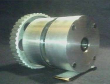
- The Disk Sensor allows you to change valve profiles, fuel injection timing and spark ignition using reading/writing magnetic heads. A computer controlled electric motor mated to the rear of the sensor turns the disk while the engine is off to set the newly elected profiles. A locking pin allows the user to disengage the pulley and timing belt so that the electric motor can turn the disk freely without turning the crank pulley and thus the new profiles may be written while the engine is off.
- It is possible to write the new profiles onto separate tracks while the engine is running and then switch to those tracks, but this would not allow the user to test the valves performance while the engine is off. The electric motor not only allows the Disk Sensor to write its own signals, but the computer controlled electric motor isolates and allows the user to measure one particular valves performance in the engine by rotating the disk at half of the maximum engine crank rotation or simulating max engine rpm. Thus testing the operation of the single valve mounted in the engine while the engine is off, at maximum cycles, gives the user the best ability to measure the singled out valves seating quality and also determine the actuator/valve longevity based off of its new profile while installed on an assembled engine. You don't want to have to tune a camless engine by pulling the head off the engine and setting it on a bench and testing from there (not practical). Once the desired valve profile is found, save and apply to all other applicable functions, such as the programming of all of the intake valves at once after isolating and tuning the selected valve. The user then may move on to set the exhaust valve, EFI and IGN.
- Changing the valve profiles in the Disk Sensor is similar to "grinding" a new camshaft each time, not to mention installation time. The rapid testing of thousands of combinations may be obtained quite easily for the OEM, the performance enthusiast, the dealership mechanic, and the weekend racer. The Disk Sensor will allow each engine to reach its peak performance whether it is turbocharged or naturally aspirated.
- Note* If an electronic engine valve profile is changed while the engine is running without the proper parameter limitations, one could not accurately tell if the valves seating noise has increased or decreased. This may affect the longevity of the valve actuator. Noise is just one testing method. Laser positioning feedback is another.
Basic program instructions :
- 1. Select the number of cylinders, firing order and input all valve timing intervals for all intake and exhaust valves
- Select the maximum lift for the intake and exhaust valves
- A Basic profile appears for the intake valve, click and drag to tune the shape of the valve profile
- Write profiles to disk in Disk Sensor
- Make sure your cylinder you are testing in, is at bottom dead center to allow for piston to valve clearance. Thread a microphone in the spark plug hole. This will measure the valve seating noise in the cylinder in the pre run test. Every engine combination and valve actuator type will have different results, but the point is to reduce the noise as much as possible in each setup while achieving the desired lift in the proper interval
- After the profiles have been written we can begin the pre run test. The electric motor rotates the disk thus outputting signals to the valve while the engine is off. Now one can measure the noise of the valve seating while the sensor is revved to maximum simulated rpm with the selected profile. The noise can be recorded and tuned by repeating this step. This is fast and easy, all while on the vehicle. This test may also be performed with a head of an engine on a test bench, but shows the testing capability on the vehicle with minimum efforts, especially when considering the work to replace the camshaft just once, in addition, although the Disk Sensor may seem like more work to someone who is more inclined to just change the internal workings of an engine computer, the computer is still inadequate in delivering the performance compared to the streaming parallel output of the Disk Sensor in conjunction with an engine computer in a final product. And
- When your done tuning the valves profile and you have achieved an acceptable noise level/ per valve type, copy the profile to the other valves, write all tracks, reinstall the locking pin and engage the timing pulley so now the engine can run on the tuned profiles. Now you can Dyno and measure the results.
*Never before could you measure the noise of the valve seating by itself so easily. The Disk Sensor allows a user to create a "cam on demand" while parked on a dyno with the gas analyzer.
**
If the valve is closing too quickly and the noise is above the acceptable threshold, then click the closing portion of the valve profile and drag towards 0 lift to reduce the lift at a particular set of degrees ensuring the valve closes quickly and early enough for a soft valve landing. Valve type highly affects closing characteristics.

|