Effectively Increase Engine Computer Processing Power
-
Current problem: Lack of input to the camless engine computer to determine valve timing. Now that the camshaft is gone, so is the camshaft sensor and its timed output which is used for fuel injection and ignition timing. This camshaft sensor displacement also effects the engine computers ability to time the camless engine valves because it no longer measures the 720 degree interval. Therefore, the engine computer must measure the crank rotation twice, using one sensor, and then calculate all of the intervals for fuel injection, ignition and valve timing from software in real-time with one streaming square wave output. This lack of input to the engine computer adds to the computers cost, complexity, production time and ultimately increase the chance of engine failure.
Automotive manufacturers have noted that the valve actuators themselves are not what is holding the camless engine back, it is the computer (software/hardware) in which is used to control such actuators that is holding back this technology.
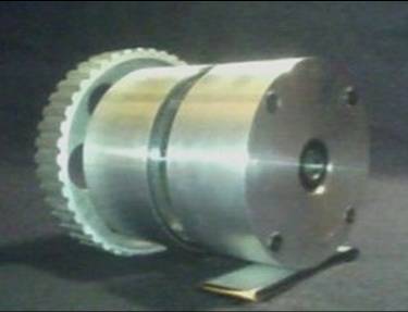
- Solution : Geer Technologies Disk Sensor. The Disk Sensor outputs all of the fuel injection, ignition and valve profiles Precisely, Repeatedly, Reliably and Simply all in Real Time. The Disk Sensor is physically connected via a belt and timed to the crank 2:1 just like a camshaft is reliably timed to the crankshaft. The Disk Sensor is the
hardware that is needed to support the software.
- The Disk Sensor eliminates the valve timing challenges that are presented to a camless engine computer using only one crankshaft position sensor.
- The Disk sensor significantly helps the engine computer start a camless engine: when starting a camless engine, the valve timing input to the engine computer and the actual valve output during starting or cranking is very important for many reasons. Current camless engine systems use a system that employs a crankshaft position sensor to time the electronic engine valve function. In this system the engine computer must be zeroed to begin to control the electronic valve sequence. This means the engine must be cranked without valve instruction until the crankshaft and engine computer have been zeroed and then the ignition and fuel injection can be timed, and in this case the electronic valve function as well. When a camless engine is shut off, the sensors and computer power is gone, and the engine continues to rotate still, just momentarily. So when the engine is starting the computer does not know where the crankshaft has stopped because the sensors and computer lost power and count. This means the engine computer cannot determine the valve positions because it must locate the crankshaft position first. This setup results in limited valve control if any, until the crankshaft has reached 0 degrees to begin controlling the valves using the engine computer and the crankshaft position sensor. This lack of input could lead to internal engine damage or a high cranking load.
- Solution to above problems: The Disk Sensor. When the ignition is turned on, the Disk Sensor immediately responds to the information on the magnetic platter and the electronic engine valves move into position before the engine starts cranking. This pre-start camless engine valve placement ensures that the engine can crank safely and efficiently. More specifically, in the Disk Sensor, one track is specifically dedicated to the 720 increment timing interval for the computer timing function and other systems. One such system using the 720 increment track is the in the starting system. The 720 increments (0 to 720) on a 360 wheel, is used for immediate valve placement. This timing track uses an optical or magnetic reading device. In the magnetic platter Disk Sensor, the magnetic heads read the magnetic media signal strength in millivolts from 0 to the 720 th increment on the 360 degree track. As the tracks increment increases from 0 to 720, so does the voltage signal produced from the track. If the magnetic head sensor detects 418 mv from the platters track while the engine is off, key on, this indicates a particular position for the crankshaft and valve position and that voltage (418mv for ex.) is referenced to a table to identify the engine position in degrees, say 320 degrees, of which the valves will have a specific placement and at such point will fall into position.
- As soon as the engine has turned the slightest by the starters activation or by a starterless system which closes some selected valves and injects those cylinders with fuel and by igniting such cylinders, all of which can be programmed by such technique provided above, the Disk Sensor starts to produce regular valve, fuel, spark timing, etc.. signals from the large quantity of individual tracks of which are dedicated to such specific outputs. The minimum or base reference voltage is used to position the valves to open a specific amount during startup thus allowing startup. Additionally the voltage applied to the valves during starting will be similar to the base voltage during idle. The computer also adjusts the valves voltage and movement according to temperature and other sensors input, but these other sensors will have much less effect on the valve opening/closing when compared to the effective voltage increase/decrease from the throttle position sensor input.
- The hardware based Disk Sensor easily outputs over a hundred streaming signals so the engine computer can reliably and accurately time the electronic engine valves, fuel injection and spark timing in the correct timing interval. The engine computer simply waits for the input signals which are produced by the disk platter in real time, timed directly to the crankshaft. Without the Disk Sensor, the engine computer has only one input of which must be decoded into 720 degrees from 2 crankshaft revolutions and potentially control over 80 independent signals with not even a camshaft sensor. (64 signals for 32 valve engine (2 signals per actuator) + 8 signals for fuel injection + 8 signals for spark ignition = 80 signals).
- The Disk Sensor is a cost effective, simple and reliable system.
- Save design time, money, increase quality and gain company performance

|
|
|